Task
1.1 For GUI access please complete Lab 1.
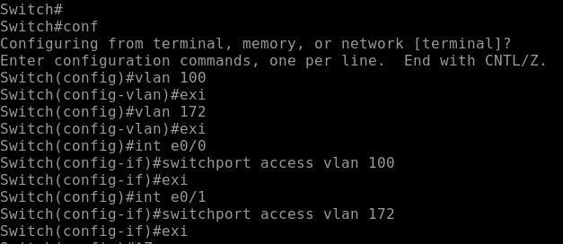
1.2 Configure switch SW01 create vlan 100 and vlan 172. Assign interface in it. In vlan 100 add Ethernet0/0 and in vlan 172 add Ethernet0/1.
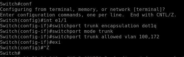
1.3 On Switch configure interface Ethernet1/1 as Trunk Interface.
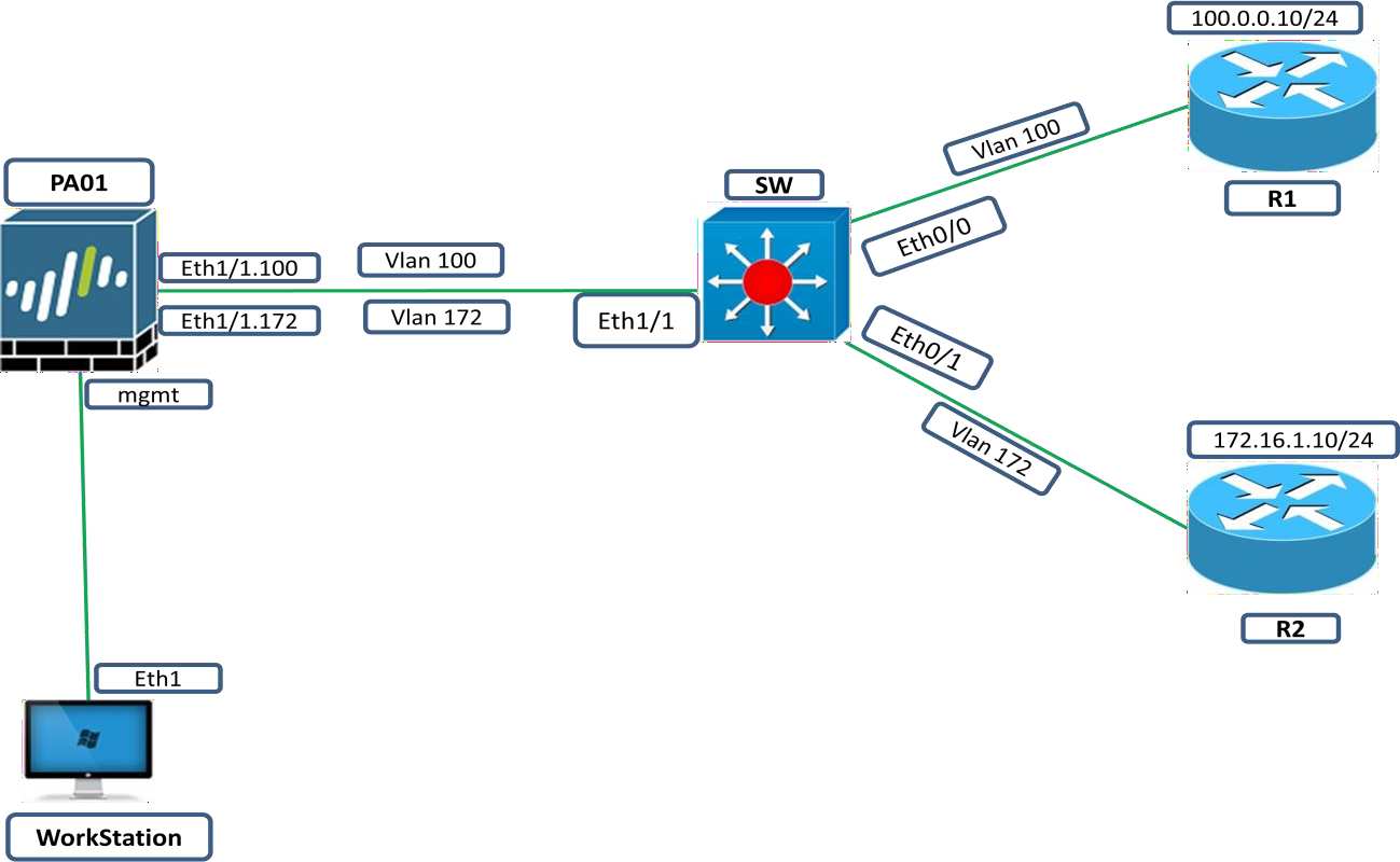
1.4 Configure PaloAlto01 interface Ethernet1/1 and divide it logically by creating Sub interface.
Explanation
Suppose you are running out of interface in your firewall then one option is there Sub-interface. Functionality of sub-interface will be same as normal layer 3 interface. Just you have to divide layer 3 interface into logical interfaces. While configuring Sub-interface make sure you don’t forget to put tag information which is used for differentiate different vlan’s data, because physically it’s a single interface that we have divided into multiple logical interfaces then how it will differentiate data of different subnets by using vlan information that we will put it as Tag information while configuring it.
Configuration
Configure Vlan on switch
Create Trunk Interface on Switch
Now its time to configure our PaloAlto01
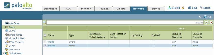
Create Zones Under Network Tab
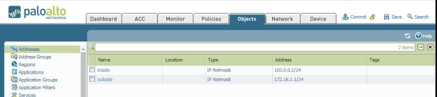
Create address Objects under Object Tab
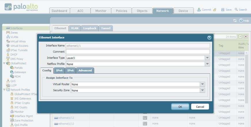
Now go to Interface section under Network Tab
Select Interface then change its interface type to layer 3 then click ok.
It will look like
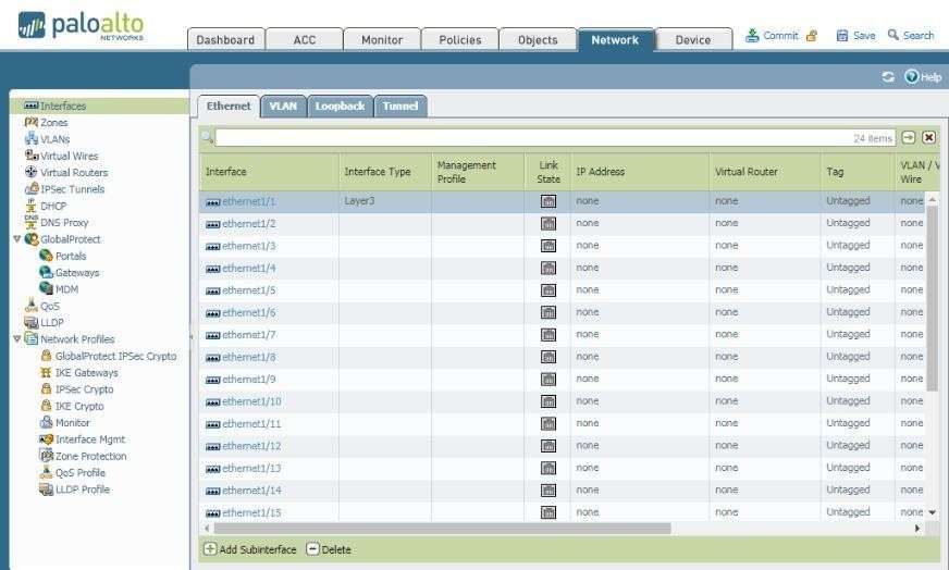
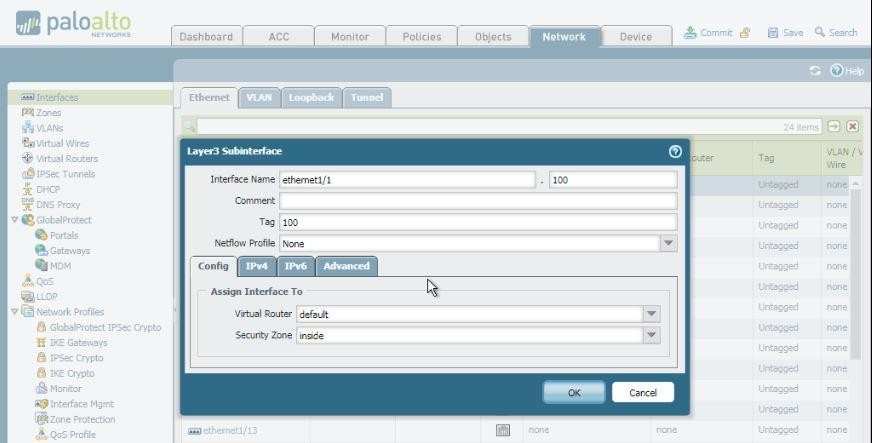
Click on Add sub interface a window will be open.
Here Ethernet1/1.100 will be sub interface number, in Tag field enter Vlan value 100 Security zone “Inside”.
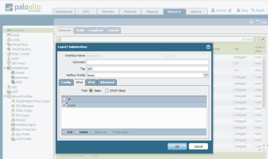
Click on IPv4 tab and select address object that we have created earlier.
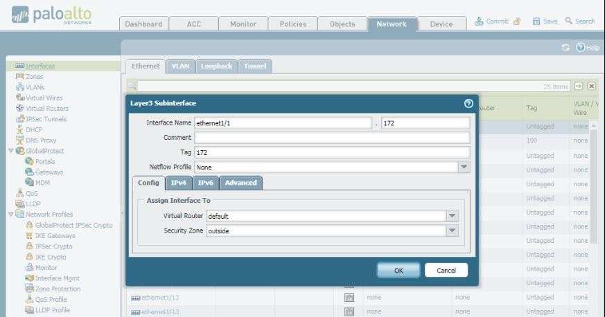
Similarly create another Sub interface by clicking on add sub interface Fill information as shown below
Click ipv4 and select address object
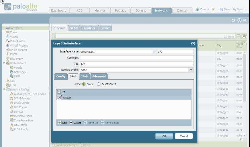
Click ok
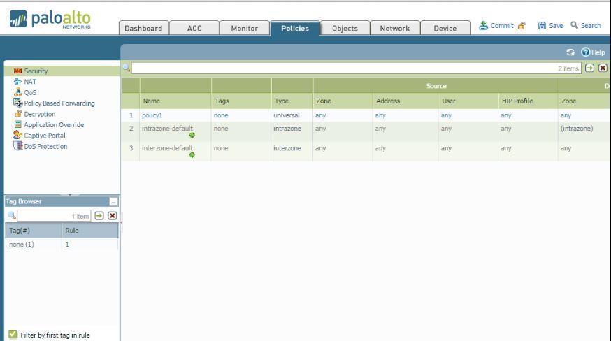
Now it’s time to create security policy so that traffic can be inspected and the pass through the firewall.
Under Policies tab security section.
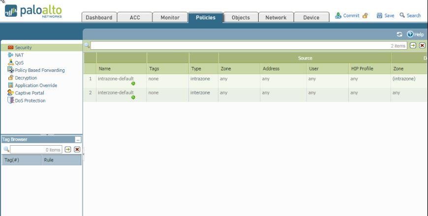
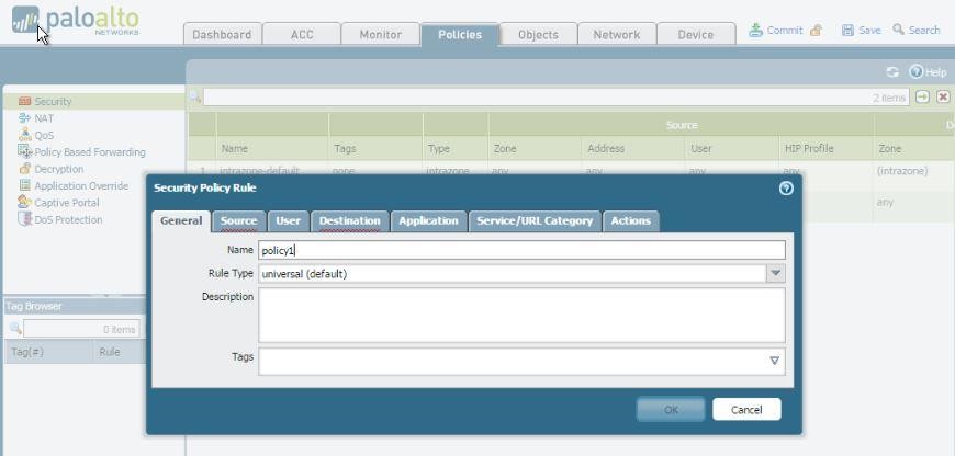
Click on add button to create a security policy. Name it Policy1
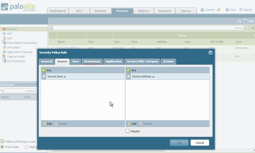
Here I marked source any but you can also select inside zone in source
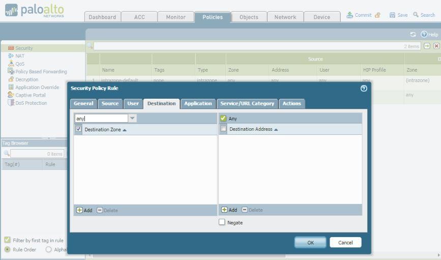
In destination zone also marked any you can select outside.
Final Security policy will be look as shown below:
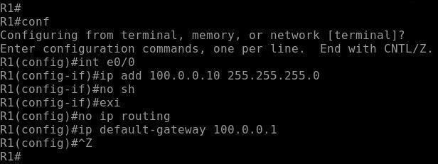
Now it’s time to configure Router R01
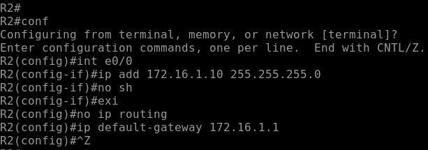
Similarly, Router R02
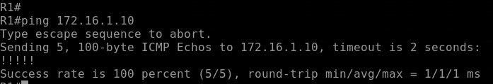
Verification:
Now it time for Verification that a single physical interface is able to work as two logical interfaces and able to flow traffic from one zone to another zone.
Ping 172.16.1.10 i.e. Router R02 ip present outside zone
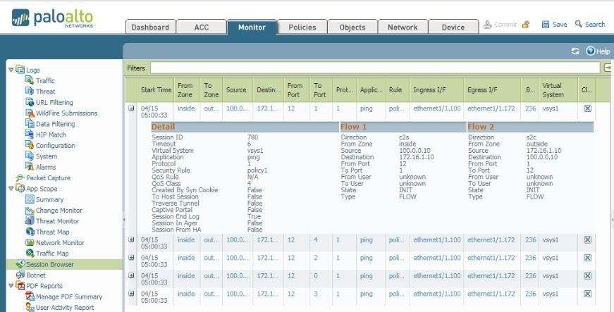
Check session on PaloAlto01 under monitor section:
In below Screenshot we can Cleary see the ingress interface and Egress interface is ethernet1/1.100 and ethernet1/1.172 respectively.