Task
1.1 For GUI access of PaloAlto01 Please complete Lab 1.
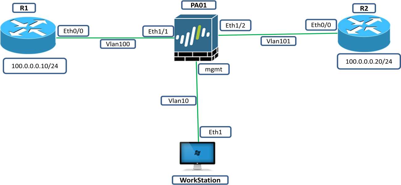
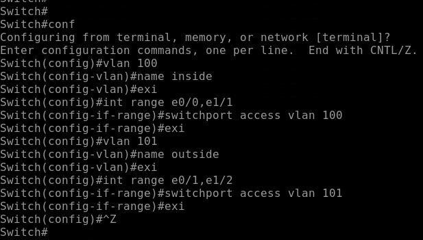
1.2 1.On Switch Create vlan 100 and vlan 101. Assign interface Eth0/0 and Eth1/1 in Vlan 100, Then interface Eth0/1,Eth1/2 in vlan 101.
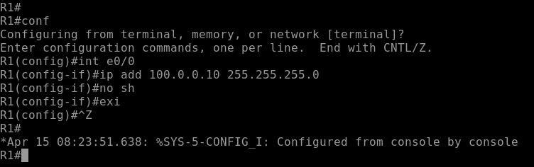
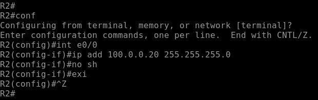
1.3 On Router R1 configure Ip address 100.0.0.10/24 and on Router R2 configure IP address 100.0.0.20/24.
1.4 Configure PaloAlto interface Eth1/1 and Eth1/2 and select type of interface Virtual Wire.
Explanation
In a virtual wire, we deploy firewall transparently in a network segment by binding two firewall interfaces together.
Virtual wire deployment is only done when we want to integrate a firewall into a topology seamlessly and the two connected interfaces on the firewall need not do any switching or routing. For these two interfaces configuration we also call it bump in the wire.
A virtual wire deployment simplifies firewall installation and configuration because you can insert the firewall into an existing production network topology without assigning MAC or IP addresses to the interfaces, no headache of redesigning the network, or reconfiguring surrounding network devices.
Each virtual wire interface is directly connected to a Layer 2 or Layer 3 networking device or host. The virtual wire interfaces don’t have any Layer 2 or Layer 3 addresses. When one of the virtual wire interfaces receives a frame or packet, it ignores any Layer 2 or Layer 3 addresses for switching or routing purposes, but applies your security or NAT policy rules before passing frame or packet over the virtual wire to the second interface and on to the network device connected to it.
By default, a virtual wire interface forwards all non-IP traffic it receives.
Configuration
Firstly, on Switch we will configure vlans as shown below
Take GUI of the PaloAlto01 from Workstation https://10.0.0.1
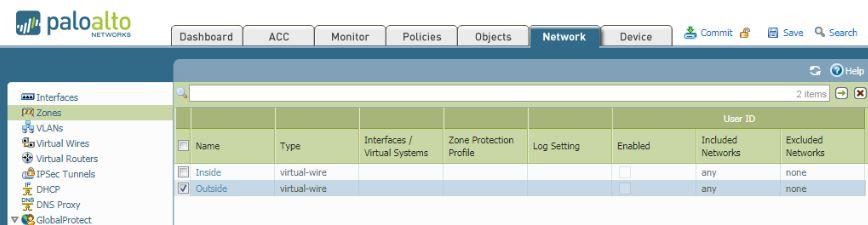
Click on Network tab and the open Zone section
Create Two Zones i.e. inside and outside as shown in screenshot
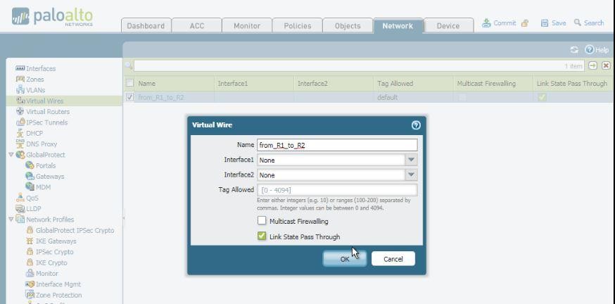
Now go to Virtual Wire Section and create a virtual wire as shown in screenshot.
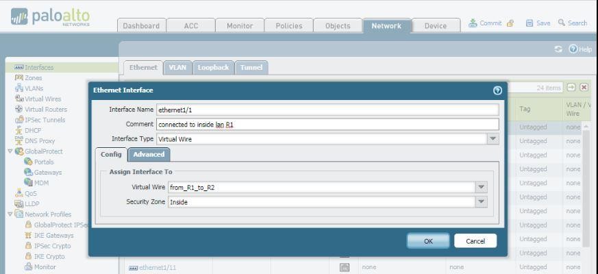
Now go to interface section selection Ethernet1/1 and configure it as shown below.
Interface type: Virtual Wire, then select virtual wire that we have created above and select zone inside.
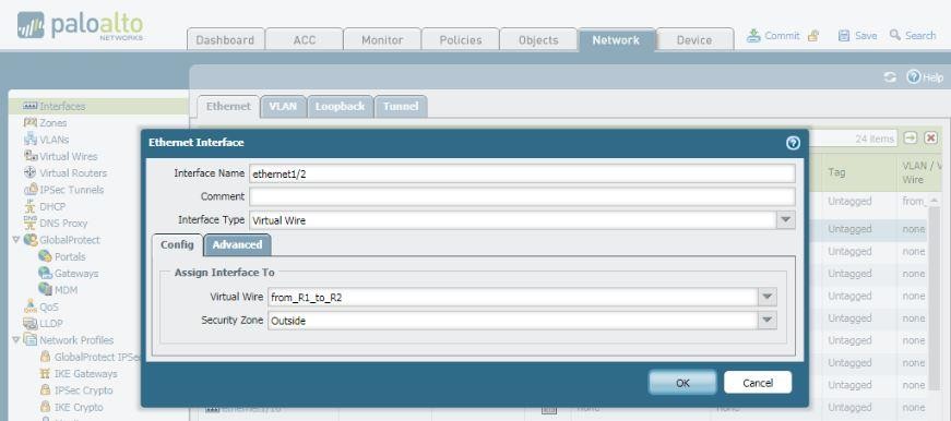
Similarly, for Ethernet1/2
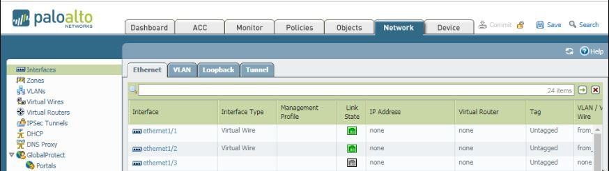
Interface Section will look like this.
Now create a security policy for traffic to be inspected by the firewall.
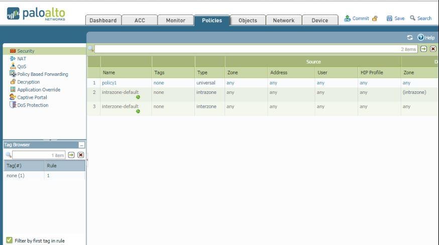
Under Policies tab security section.
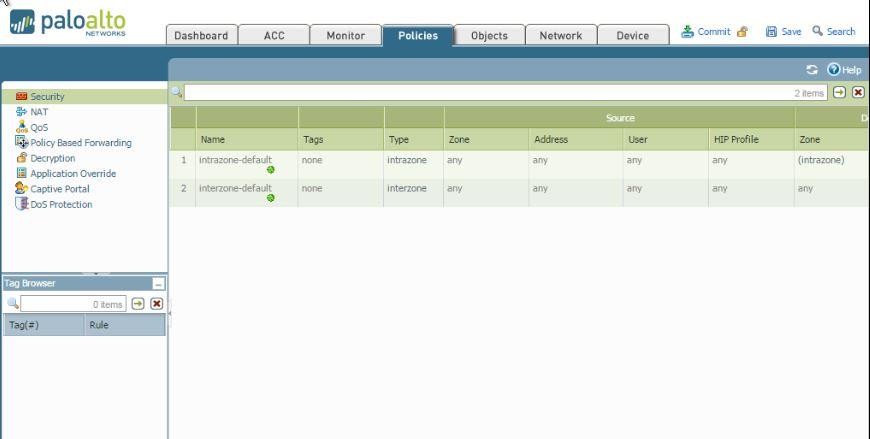
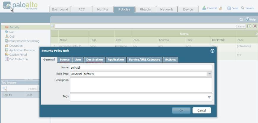
Click on add button to create a security policy.
Name it Policy1
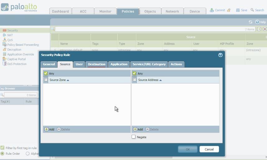
Here I marked source any but you can also select inside zone in source
In destination zone also marked any you can select outside.
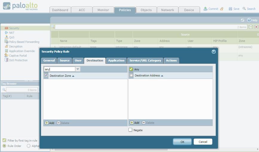
Final Security policy will be look as shown below:
Its time to configure Router R01
Configuration for R02
All done with the configuration part
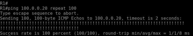
Verification:
From R01 ping 100.0.0.20 that is ip address of R02
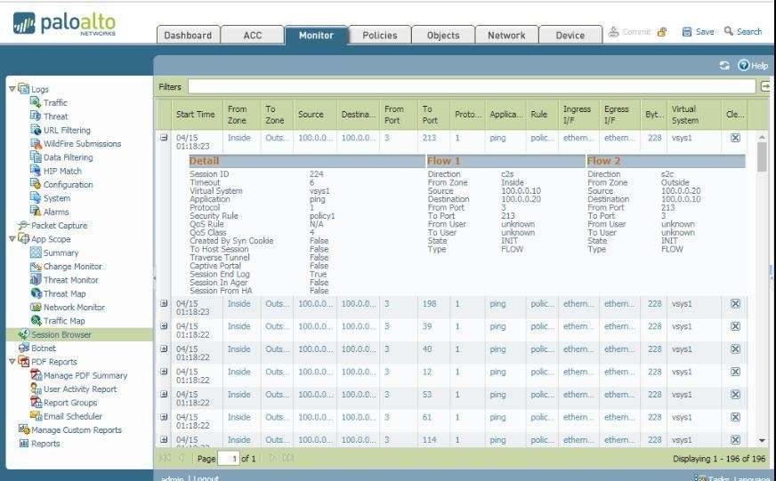
Verification on PaloAlto01
Check session under monitor tab.
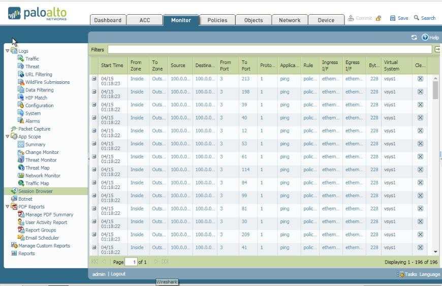
Here we can see detailed information of sessions: